 |
XYZ linear axis hollow cooling screw drive
B\C rotary shaft DD direct drive transmission
Full closed loop absolute value measurement system
Scope of supply
Standard accessories function table (please refer to the controller function for the electric control part)
| No | Item | Unit | Qty |
| 1 | mainframe castings | tower | 1 |
| 2 | Siemens840DSL control system | set | 1 |
| 3 | Display: 19LCD | set | 1 |
| 4 | FH five-axis multi-function swing head (B-axis) | set | 1 |
| 5 | HCS-190Lg Milling Spindle | Only | 1 |
| 6 | X/Y/Z Axis Hollow Cooled Ball Screws | piece | 3 |
| 7 | Mill/Turn Direct Drive Rotary Table (C-axis) | set | 1 |
| 8 | B axis RCN8380 29 bits absolute encoder | Only | 1 |
| 9 | C axis RCN2580 28 bits absolute encoder | Only | 1 |
| 10 | BOSCH REXROTH Roller Linear Slides | set | 7 |
| 11 | Electrical box temperature control device | set | 1 |
| 12 | Spindle water cooling system | set | 1 |
| 13 | Machine tool ring water spray | set | 1 |
| 14 | Five-axis head crescent water spray, crescent blowing | set | 1 |
| 15 | Front and side working door safety interlock system | set | 1 |
| 16 | Waterproof work bin lighting | Only | 2 |
| 17 | hydraulic station | set | 1 |
| 18 | Central centralized feed lubrication device | set | 1 |
| 19 | Operation side cleaning water gun and air gun | set | 1 |
| 20 | Cutting fluid system | set | 1 |
| 21 | Fully enclosed protective sheet metal | set | 1 |
| 22 | Operation box | set | 1 |
| 23 | Electrical Cabinet Cooling Unit | set | 1 |
| 24 | Siemens electronic handwheel | Only | 1 |
| 25 | Foot-operated spindle knife release switch | Only | 1 |
| 26 | Machine tool tri-color light | set | 1 |
| 27 | 40 HSK-A63 tool magazines and servo automatic tool changing system | set | 1 |
| 28 | X/Y/Z three-axis absolute value grating scale | set | 3 |
| 29 | Spiral Chip Roller and Rear Chip Conveyor Chip Carriage | set | 1 |
| 30 | Renishaw RMP60 infrared probe unit | set | 1 |
| 31 | Renishaw TS27R tool setter unit | set | 1 |
| 32 | Foundation level pads and foundation bolts | set | 1 |
| 33 | technical manual | set | 1 |
|
Parameters
| Model | Unit | 60 P | 80 | 100 |
| Travel |
| X axis travel | mm | 600 | 800 | 1000 |
| Y axis travel | mm | 800 | 1050 | 1150 |
| Z axis travel | mm | 600 | 800 | 1000 |
| Distance from spindle nose to work table surface | mm | 150-750 | 162-962 | 160-1160 |
| Horizontal milling head | mm | 30-630 | 39-839 | 30-1030 |
| Feed/fast moving speed | m/min | 40 | 40 | 40 |
| Feed force | KN | 10 | 10 | 10 |
| Rotary table (C axis) |
| Working table size | mm | Ø630 | Ø855 | Ø1050 |
| Max.table load (mill) | kg | 2000 | 3000 | 4000 |
| Max.table load (turning) | kg | 1000 | 2000 | 3000 |
| Minimum split angle | ° | 0.001 | 0.001 | 0.001 |
| Rated torque | Nm | 807 | 1140 | 1330 |
| maximum torque | Nm | 1430 | 1980 | 2630 |
| CNC swing milling head (B axis) |
| Swing range (0=vertical/180=horizontal) | ° | -15~180 | -15~180 | -15~180 |
| Rapid traverse and feed rate | rpm | 80 | 50 | 103 |
| Minimum split angle | ° | 0.001 | 0.001 | 0.001 |
| Rated torque | Nm | 743 | 743 | 1050 |
| maximum torque | Nm | 1320 | 1320 | 2130 |
| Spindle |
| Spindle speed | rpm | 12000 | 16000 | 10000 |
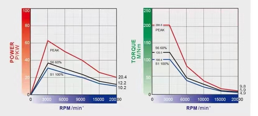
| Spindle power | Kw | 34/42 | 31/36 | 42/58 |
| Spindle torque | Nm | 132/145 | 100.4/120.5 | 215/350 |
| Spindle tapre | | HSKA63 | HSKA63 | HSKA100 |
| Tool magazine |
| Tool interface | | HSKA63 | HSKA63 | HSKA100 |
| Tool magazine capacity | PCS | 40 | 40 | 40 |
| Maximum tool diameter/length/weight | | Ø85/300/8 | Ø85/300/8 | Ø135/300/12 |
| Tool change time (tool to tool) | S | 1.8 | 1.8 | 2 |
| Measuring device |
| Infrared probe | | Rensishaw RMP60 | Rensishaw RMP60 | Rensishaw OMP60 |
| Tool detection instrument in working processing area | | NC4F230 | Rensishaw TS27R | NC4F230 |
| Position accuracy (ISO230-2 and VDI3441) |
| X/Y/Z positioning accuracy | mm | 0.005 | 0.008 | 0.006 |
| X/Y/Z Repeat positioning accuracy | mm | 0.004 | 0.005 | 0.004 |
| B/C positioning accuracy | | 8" | 10" | 8" |
| B/C Repeat positioning accuracy | | 4" | 4" | 4" |
| CNC controller |
| CNC system | | Siemens840D | Siemens840D | Siemens840D |
| Other |
| Machine weight | Kg | 15000 | 20000 | 21000 |
|
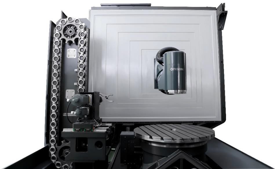
3.1 Main Machine Specifications | Optimum Rigid Structure Configuration
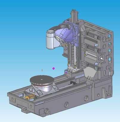 Design Features | Best Mechanical Wire Casting Analysis Design
◆Full box-type thermo symmetric casting structure, using Meehanna grade high-grade cast iron
◆Tempering and natural aging treatment to eliminate internal stress
◆Structural natural frequency vibration eliminates material processing stress
◆Comprehensive wall and large-area high-rigidity column design can effectively improve rigidity and static and dynamic accuracy
◆Three-axis hollow cooling screw drive
Design Features | Best Mechanical Wire Casting Analysis Design
◆Full box-type thermo symmetric casting structure, using Meehanna grade high-grade cast iron
◆Tempering and natural aging treatment to eliminate internal stress
◆Structural natural frequency vibration eliminates material processing stress
◆Comprehensive wall and large-area high-rigidity column design can effectively improve rigidity and static and dynamic accuracy
◆Three-axis hollow cooling screw drive
|
3.2 Electric Spindle
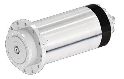 Design Features
◆According to the characteristics of their own machines, independent research and development and production.
◆The taper hole of HSK-A63 is adopted in the 80P-C model.
◆Adopt external cooling system for circulating cooling, which can effectively ensure the application of electric spindle.
Design Features
◆According to the characteristics of their own machines, independent research and development and production.
◆The taper hole of HSK-A63 is adopted in the 80P-C model.
◆Adopt external cooling system for circulating cooling, which can effectively ensure the application of electric spindle.
|
3.3 CNC swing milling head (B axis)
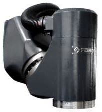 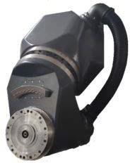 Design Features
◆Independent design and production.
◆Built-in DD motor zero transmission chain no backlash design.
◆High acceleration characteristics.
◆The shortest span between the tool nose point of the spindle and the structural support point realizes the maximum rigidity of cutting.
◆Larger YRT bearing improves rigidity.
◆ Equipped with HEIDENHAIN RCN8380 series absolute rotary encoder measurement system, fully closed-loop control, to ensure the best accuracy.
◆B-axis cooling system design reduces heat transfer.
Design Features
◆Independent design and production.
◆Built-in DD motor zero transmission chain no backlash design.
◆High acceleration characteristics.
◆The shortest span between the tool nose point of the spindle and the structural support point realizes the maximum rigidity of cutting.
◆Larger YRT bearing improves rigidity.
◆ Equipped with HEIDENHAIN RCN8380 series absolute rotary encoder measurement system, fully closed-loop control, to ensure the best accuracy.
◆B-axis cooling system design reduces heat transfer.
|
3.4 Rotary table (C-axis table)
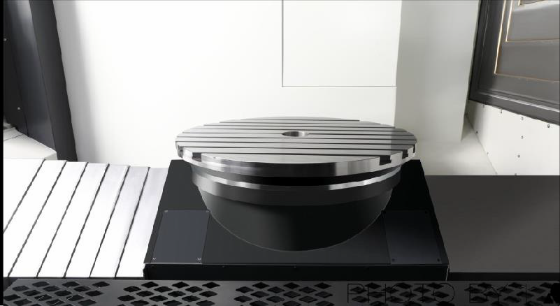 Design Features
◆Independent design and production.
◆Built-in DD motor zero transmission chain no backlash design.
◆High acceleration and deceleration response characteristics.
◆Larger YRT bearing increases rigidity.
◆Large rated driving torque, positioning and processing with table positioning and clamping device
◆Meet the needs of milling, reduce workpiece handling and improve product accuracy.
◆Equipped with HEIDENHAIN high-precision rotary encoder measurement system, fully closed-loop control to ensure the best accuracy.
◆Cooling system design to reduce heat transfer.
Design Features
◆Independent design and production.
◆Built-in DD motor zero transmission chain no backlash design.
◆High acceleration and deceleration response characteristics.
◆Larger YRT bearing increases rigidity.
◆Large rated driving torque, positioning and processing with table positioning and clamping device
◆Meet the needs of milling, reduce workpiece handling and improve product accuracy.
◆Equipped with HEIDENHAIN high-precision rotary encoder measurement system, fully closed-loop control to ensure the best accuracy.
◆Cooling system design to reduce heat transfer.
|
3.5 Control system
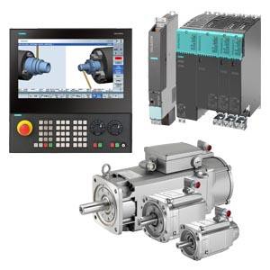 Selection features
◆Select the control host NCU730.3B for five-axis linkage (see the function table for details of the system configuration)
◆With RTCP function
◆Choose Siemens S120 drive with 3 times overload capacity and 1FT series motor with high kinematic characteristics.
◆Select TCU30.3+ICP427E as HMI interactive host, IPC has higher computing speed and higher storage space.
Selection features
◆Select the control host NCU730.3B for five-axis linkage (see the function table for details of the system configuration)
◆With RTCP function
◆Choose Siemens S120 drive with 3 times overload capacity and 1FT series motor with high kinematic characteristics.
◆Select TCU30.3+ICP427E as HMI interactive host, IPC has higher computing speed and higher storage space.
|
3.6 Automatic tool changing system
 Design Features
◆Independent design and production.
◆Tool selection and tool change use servo motor to control the terminal action, which is more stable and accurate.
◆Combined with the tool management function of Siemens840DSL, more efficient tool management.
Design Features
◆Independent design and production.
◆Tool selection and tool change use servo motor to control the terminal action, which is more stable and accurate.
◆Combined with the tool management function of Siemens840DSL, more efficient tool management.
|
3.7 Liftable tool setter
Design Features
◆Equipped with Ransishaw TS27R tool setter with higher precision.
◆Automatic tool setting on the machine, automatic update of tool compensation.
◆The tool setting device can be raised and lowered to save the space of the processing surface.
◆Fully sealed sheet metal design to protect the tool setter from damage by water and iron filings during processing.
|
3.8 Infrared probe
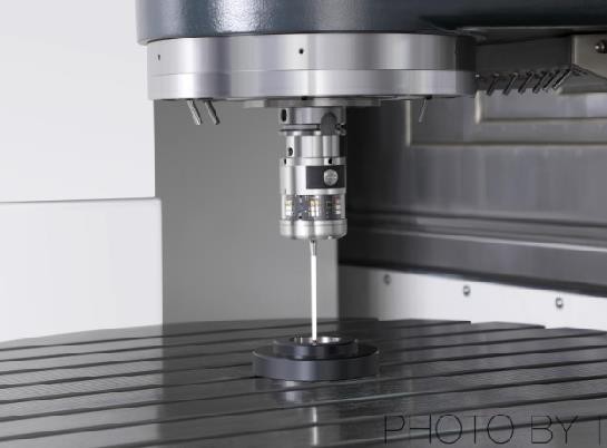 Design Features
◆Equipped with Ransishaw RMP60 trigger optical probe.
◆On-machine workpiece alignment and size inspection can reduce manual inspection errors and improve product accuracy and processing efficiency.
◆90% savings in on-board assistance time.
Design Features
◆Equipped with Ransishaw RMP60 trigger optical probe.
◆On-machine workpiece alignment and size inspection can reduce manual inspection errors and improve product accuracy and processing efficiency.
◆90% savings in on-board assistance time.
|
3.9 Safety protection sheet metal
|
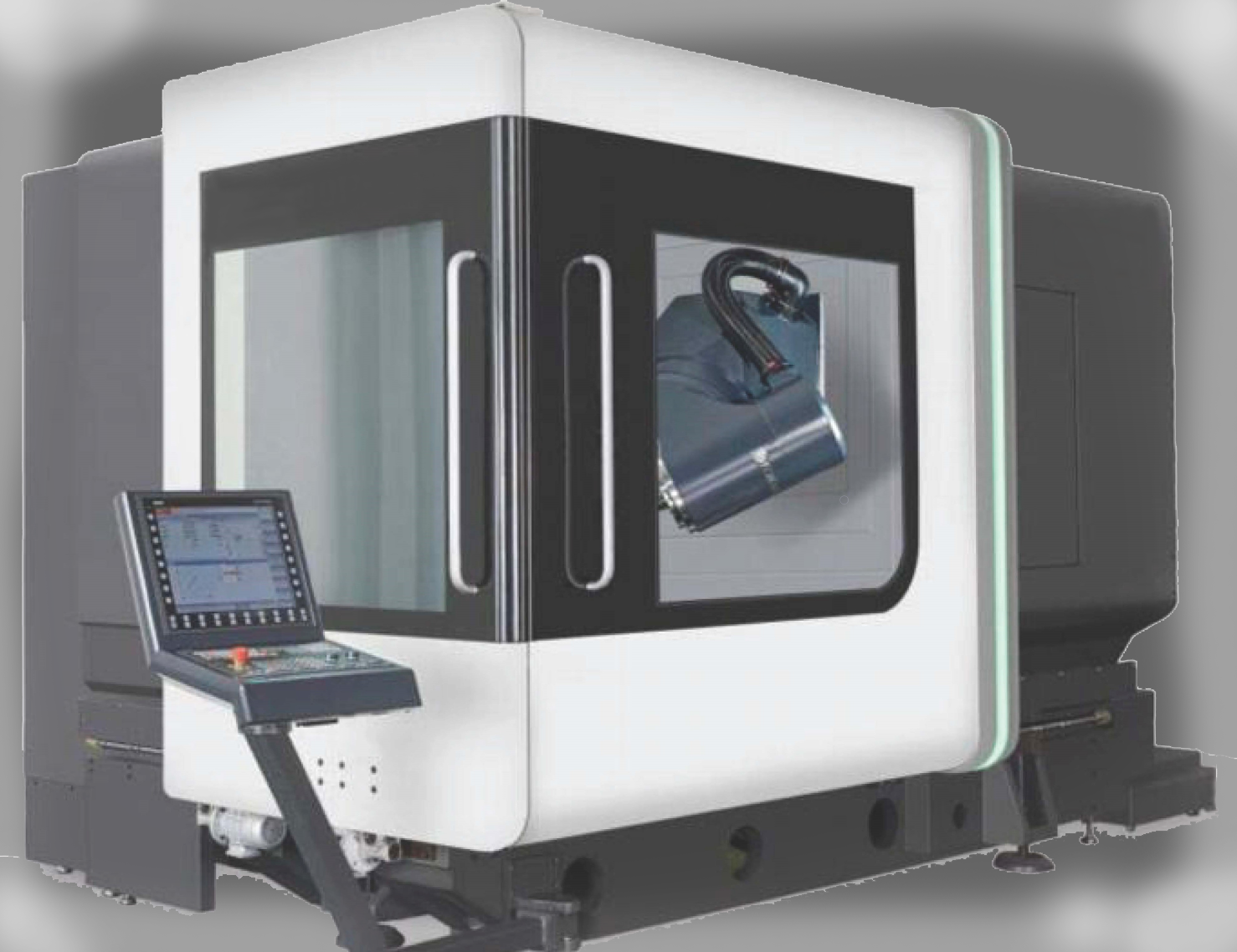
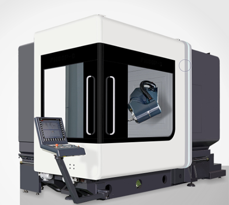
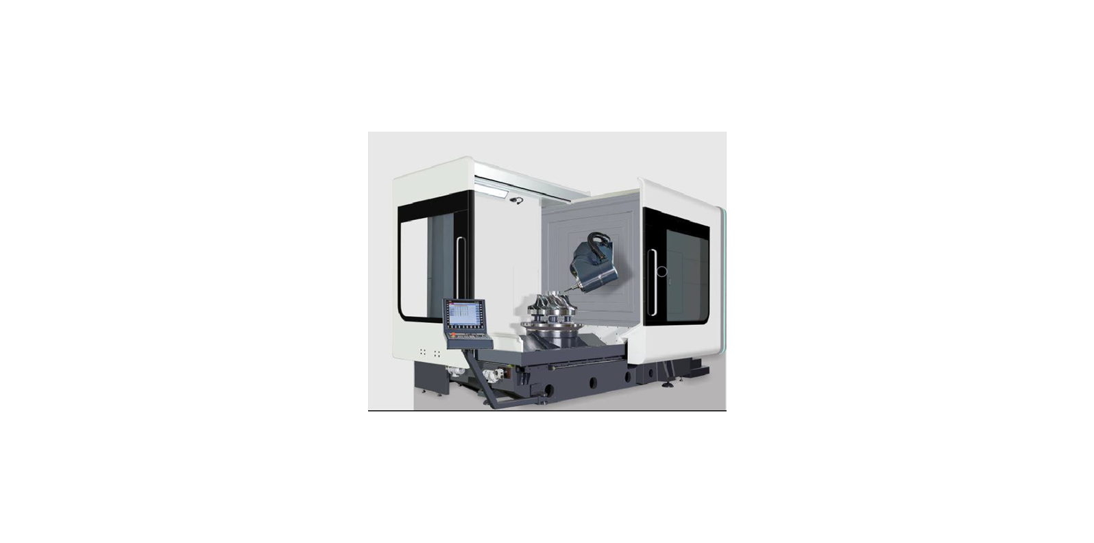
3.10 Appearance
The cover design of the FH series five-axis machining center complies with the strict CE safety standards. The fully dense sheet metal prevents the operator from entering the work area by mistake during processing, and at the same time prevents the use of high-pressure cutting fluid or chips from the machine, except for the warning nameplate. , The operation door is also equipped with a safety switch to prevent accidents during operation or maintenance. And has a large peep window, which is convenient for the operator to understand the operation and processing of the machine.
|
3.11 Cleaning
 Use the telescopic cover and protective sheet metal to protect the chips generated during operation, avoid cutting splashes and cause damage to other mechanisms
|
3.12 Lighting
The working area is equipped with two LED lights, and the illuminance of the lighting is maintained above 800LUX, providing a suitable bright working environment for the operator.
|
3.13 Operability
The operation side is equipped with a split-type sliding door, which provides a large opening space, which is convenient for the workpiece to be freely loaded and unloaded from three directions using the crane.
|
4.1 Environmental parameters
| project | Environmental parameter conditions | Remark |
| temperature | 17℃~25℃ (during operation) | In order to keep the accuracy of the machine tool within the specified range, the optimum ambient temperature requires 17°C to 25°C, and the temperature difference does not exceed ±2°C/24h. Allowable range 15℃~40℃ Ideal operating ambient temperature ±2℃. |
| 0℃~60℃ (during transportation) |
| humidity | 40%~70% at 20℃ | No condensation |
| vibration | Below 0.5G | |
|
4.2 Installation site requirements
1) The device must not be installed in the range of radiation such as: microwaves, ultraviolet rays, lasers or X-rays.
2) In order to ensure the machining accuracy of the machine tool and reduce the temperature difference around the equipment, please do not install it in the following areas:
◆Direct sunlight
◆High humidity
◆Large temperature difference
◆Vibration
◆Strong magnetic field
◆Dust
3) Avoid the following situations around the installation area of the equipment:
◆ Garage
◆A lane with frequent car traffic
◆Pressure or stamping equipment
◆ Electric welding, spot welding or hydrogen arc welding
◆Substation
◆High voltage line
◆Equipment or processing that easily generates dust
4) The foundation of the equipment installation site needs to be designed and constructed according to the provisions of GB 50040-1996 "Code for Design of Power Machine Foundation".
5) The installation site of the equipment must have a fixed power supply that meets the relevant requirements of the state, no temporary power supply is allowed, and the equipment must have good grounding protection. The machine tool should have reliable grounding: the grounding wire is copper wire, the wire diameter should not be less than 10mm2, and the grounding resistance should be less than 4Ω.
6) Power supply interface: The power supply provided by the equipment installation site must be a three-phase four-wire system (U, V, W, N), and the power line voltage is AC380V. Pay attention to the voltage regulation of the power supply, and ensure that the power supply voltage fluctuation does not exceed ± 5%. If the voltage in the area of use is unstable, the machine tool should be equipped with a special regulated power supply for numerical control to ensure the normal operation of the machine tool. The upper-level power switch of the equipment selects D-type 160A and no leakage type.
7) The installation site of the equipment must have a stable air source, and a set of air source purification devices (dehumidification, degreasing, and filtration) should be added before the air intake of the machine tool.
8) Compressed air interface: p=4~6kgf/cm², Q=60m³/h, reserve ¢10 quick connector at the air source interface, and reserve ¢10~m for the temporary adjustment on site. The main line of compressed air must be equipped with main line filter and dryer. The air pressure is required to be 0.5~0.7Mpa. Pressure dew point -20°C to 0°C; oil content 1PPM; dust content <50μm.
9) Party A shall reserve enough space for installation according to the appearance size of the machine tool of the equipment sample provided by Party B, so as to facilitate the installation and maintenance of the machine tool.
|